The output pins of the hardware used by RemoteSign ESP devices can only handle a minimal amount of current. Output pins can supply up to 12mA of +3.3 Volts, or they can sink (-) up 20mA each. There is only enough voltage to drive one LED per pin. All is not lost however as there are devices that can take the 3.3 Volt output to switch much bigger loads, including AC power up to 240 Volts. If the item that needs to be switched has only two states, on and off, and does not have to switched more than once per second (no dimming), then a relay is a good choice. (If rapid switching of DC is needed, use a MOSFET.)
Relays are available as single modules or you can get 2, 4 or 8 or more relays on a single board. Ensure that the relay you use can be triggered with just 3 Volts, as the RemoteSign ESP hardware only puts out 3.3V.
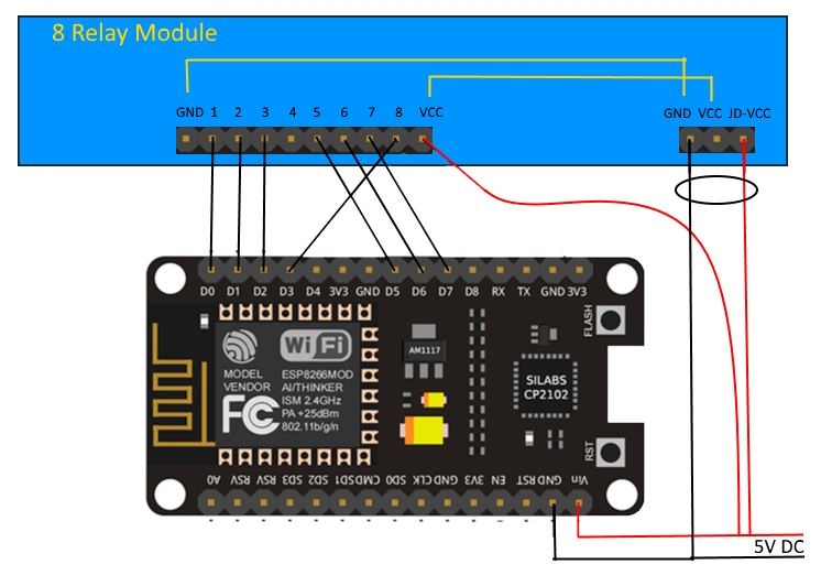
The relays typically need a 5V power supply to make them work, so connect the 5V pin to the Vin and VCC pins as well a ground wire from GND to GND. Ensure you power the RemoteSign ESP with 5V (directly to the pins or via a USB cable) and not 3.3V.
The pins that are used to drive the relays are connected to the trigger pins of each relay on the board. Here is an example of an 8 relay board connected to a RemoteSign ESP in order to drive 110V lights in a German signal.
Here is a relay I have used.