RemoteSign ESP is a flexible device that can be used to handle numerous tasks, including the following:
- Displaying a miniature OLED screen (3 sizes of screen are supported)
- Feedback sensors (up to 10 sensors each)
- Drive train light signals (up to 5 signals or 10 aspects total, fully configurable with light fade options, etc.)
- Drive a complete set of road traffic lights (with configurable delays, Euro and US/UK patterns):
- Two roads with or without pedestrian crossings
- Single road with pedestrian crossing
- Drive up to 11 LED lights with numerous lighting effects and user definable animated patterns
- Drive RGB color lights with various lighting effects
- Control a stepper motor
- Control a servo motor
The different types of functionality listed above are also supported on a single device and can be reconfigured as needed over Wi-fi using the {DCH} command (built into RemoteSign Sequencer).
In addition, scripts can be recorded and saved to the device so that they perform functions automatically on startup, or in response to commands received via Wi-Fi. RemoteSign Sequencer can be used to define what functionality is present and to record scripts or send commands, etc.
Scripts can be triggered from any Windows software that can launch an external program such as RocRail, TrainController (RailRoad & Co™), etc. or from any platform with your own software.
They are powered using either a USB cable (type B-micro) or a 5 Volt DC power supply.
The switched outputs provide +3.3V with a maximum load of 12mA per pin. This is sufficient to drive one LED or a relay or MOSFET with 3.3V trigger thresholds. How to connect a MOSFET.
WiFi connections and disconnections to/from the module from other computers do not disturb the output and can occur 'silently' in the background.
 |
| HO scale figure watching RemoteSign ESP driven platform sign |
How to connect things to a RemoteSign ESP
Version history
A list of changes over time can be seen here
Building your own RemoteSign ESP
The devices are base on on ESP8266 processors. Here is how you can build a functional RemoteSign client using your own ESP8266 or WEMOS D1 mini hardware.
Here is a 64x256 pixel display

a 32x128 pixel display: (The actual display area of the sign is about 21mm x 6mm)


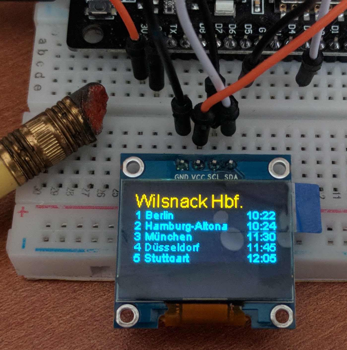
and a 64x128 display: (The actual display area of the sign is about 14mm x 12mm)
This size screen is available in Yellow+Blue or all White.

There are two methods to get the software loaded onto your ESP8266 devices.
- Using RemoteSign Sequencer on Windows (requires arduino-cli to be installed)
- Using the RemoteSign loader sketch using the arduino IDE (any platform)
Both methods require:
- ESP8266 NodeMCU or WEMOS D1 mini processor
- (optional) OLED screen, either of these:
- 128x64 OLED 0.96" screen with SSD1306 controller and I2C interface (approximate size: 22mm x 11mm actual display area on a 27mm x 27mm circuit board)
- 128x32 OLED 0.91" screen with SSD1306 controller and I2C interface (approximate size: 21mm x 6mm actual display area on a 38mm x12mm circuit board)
- 72x40 OLED 0.41" screen with SSD1306 controller and I2C interface (approximate size: 10mm x 5mm actual display area on a 12mm x17mm circuit board)
- NewHaven 256x64 OLED screen with SSD1322 controller and SPI interface (approximate size: 67mm x 13mm actual display area on a 97mm x 32mm circuit board)
- No screen option, you can use RemoteSign ESP without any screen to handle sensors, relays, lights, etc.
- USB cable to connect ESP8266 to the PC
- Wifi network with internet access
These items are readily available around the world. Your favorite online shopping web site is likely to have NodeMCU ESP8266 or WEMOS D1 mini units as well as the 0.96" OLED screens. (Ensure they are SSD1306 or SSD1322.)
Physical sizes may vary slightly.
Physical sizes may vary slightly.
Tools needed
- If attaching an OLED screen:
- Soldering iron and solder
- Some wire
- Wire cutter and stripper
Method #1
Materials needed
- RemoteSign Sequencer 3.9 (installed as part of RemoteSign Windows installation)
- Arduino-cli (free download from https://arduino.github.io/arduino-cli - download and run the Windows msi installer)
Method #2
Materials needed
- Arduino IDE (download from https://www.arduino.cc/en/Main/Software)
- Wifi Manager library (IDE will install this for you)
- RemoteSign loader, downloaded from http://ota.mixmox.com/RemoteSignLoader.ino
Steps
1. If using a screen, connect the OLED screen to your ESP8266/D1 (see connection details below)2. Install the Arduino IDE
3. Connect your ESP8266/D1 to a USB port of your computer. You may need to install a driver.
4. In Arduino IDE, set up the board manager in File-> Preferences and enter:
http://arduino.esp8266.com/stable/package_esp8266com_index.json
in the field: Additional Boards manager URLs
4. Open Boards Manager from Tools -> Board menu and install esp8266 platform. Then select either "NodeMCU 1.0 (ESP-12E Module) or LOLIN (Wemos D1 R2 and mini) , under Tools->Board

5. Install WiFiManager library
Download the zip file at https://github.com/tzapu/WiFiManager by clicking on the green CODE button and the clicking "Download ZIP"


6.
7. Download the RemoteSign loader sketch, (you may have to right click and select Save link as...) place it in a folder called RemoteSignLoader, and open it in the Arduino IDE (double click on the file RemoteSignLoader.ino)
8. Open the serial monitor (Tools->Serial monitor) so that you can see any error conditions (such as incorrect wifi password, etc.)
9. Compile and download the sketch to your ESP8266
To compile and download, click here:

Note, initially the compiler will stop with this display:

This is where you select the type of display you are using. Place // at the start of the line highlighted in pink and remove the // from the line that matches your display. Then compile and download again:

10. You can also add your WiFi network name and password by editing these lines:
// if you wish to skip the phone setup, you can enter your wifi credential here:
char ssid[] = "your wifi name"; // name of your wifi network
char password[] ="your wifi password"; // password for your wifi network
Note: nothing will display on the screen yet... but the serial monitor will tell you you need to reset the ESP8266 when it is ready for the next step.
11. Once the sketch has completed downloading, reset the ESP8266/D1
(unplug it and plug it in again)
12. If you did not enter your wifi name and password in step 10, you should now connect to the Wifi network called "RemoteSign", and provide the network name and password. Do this via smartphone/tablet (or from any browser by visiting 192.168.4.1).
Nothing can appear on the screen until it has loaded the software, so wait a minute or so until it updates itself and reboots. Once it reboots it should turn the screen on.
13. After installing RemoteSign, it will reboot and your RemoteSign should be ready. It should display its name and IP address that you can use to connect to it from another RemoteSign, such as the Windows version.

In the example above, it indicates its network name is remotesignc6cf88
You can enter that name into a copy of RemoteSign that needs to connect to it. If the connection fails add .lan or .local to its end; remotesignc6cf88.lan If that still fails use its IP address (192.168.86.172 in this example). (Note fuzzy screen is because it still has its protective cover on!)

If the screen does not switch on, check that you have connected the screen correctly and that it matches the line you uncommented in step 9. Check if it has joined your network (using your network admin tools). If it has, try connect to it with Sequencer or RemoteSign Windows. If it connects, then your screen or the connections are faulty. If it does not connect then, it has not managed to download the RemoteSign software (after step 11).
Hookup details
Here are the connection details for the OLED screens
0.96" 128x64 SSD1306 I2C


ESP display
3V VCC
GND GND
D1 SCL or SCK
D2 SDA
See here for how to connect it up.
0.91" 128x32 SSD1306 I2C

ESP display
3V VCC
GND GND
D1 SCK or SCL
D2 SDA
0.41" 72x40 SSD1306 I2C

ESP display
3V VCC
GND GND
D1 SCK or SCL
D2 SDA

NodeMCU display
GND 1 VSS
3V3 2 VDD
3 NC
D2 4 D/C
GND 5 R/W W/R
GND 6 E/RD
D5 7 CLK
D7 8 SDIN
9 NC
GND 10 GND
GND 11 GND
GND 12 GND
GND 13 GND
GND 14 GND
D1 15 /RES
D8 16 /CS
GND 17 BS1
GND 18 BS0
Connecting sensors to RemoteSign ESP
The RemoteSign ESP can report changes (sensors) on 10 input pins. By default four are defined as follows:S1 - pin D5 (GPIO 14)
S2 - pin D6 (GPIO 12)
S3 - pin D7 (GPIO 13)
S4 - pin D9/RX (GPIO 3)
To use these pins as sensors they should be grounded to the G pin of the ESP8266/WEMOS D1 mini. In other words if not grounded the sensors are off. If, say, D7 is connected to G then sensor 3 will be reported as ON by sending {S3}1 to a connected system. When D7 is no longer grounded, it will send {S3}0.

These pins can also be queried at any time using the {DR?} command. A value of 1 means it is grounded, a value of zero means it is not grounded. Do not connect these pins to any potential that differs to the G (ground) pin.
See Connecting Sensors for more details of connecting sensors (including temperature sensors).
Licence
A library used to support the screens is the u8g2 library which is Copyright (c) 2016, olikraus@gmail.comUniversal 8bit Graphics Library (http://code.google.com/p/u8g2/)
Copyright (c) 2016, olikraus@gmail.com
All rights reserved.
Redistribution and use in source and binary forms, with or without modification,
are permitted provided that the following conditions are met:
* Redistributions of source code must retain the above copyright notice, this list
of conditions and the following disclaimer.
* Redistributions in binary form must reproduce the above copyright notice, this
list of conditions and the following disclaimer in the documentation and/or other
materials provided with the distribution.
THIS SOFTWARE IS PROVIDED BY THE COPYRIGHT HOLDERS AND
CONTRIBUTORS "AS IS" AND ANY EXPRESS OR IMPLIED WARRANTIES,
INCLUDING, BUT NOT LIMITED TO, THE IMPLIED WARRANTIES OF
MERCHANTABILITY AND FITNESS FOR A PARTICULAR PURPOSE ARE
DISCLAIMED. IN NO EVENT SHALL THE COPYRIGHT HOLDER OR
CONTRIBUTORS BE LIABLE FOR ANY DIRECT, INDIRECT, INCIDENTAL,
SPECIAL, EXEMPLARY, OR CONSEQUENTIAL DAMAGES (INCLUDING, BUT
NOT LIMITED TO, PROCUREMENT OF SUBSTITUTE GOODS OR SERVICES;
LOSS OF USE, DATA, OR PROFITS; OR BUSINESS INTERRUPTION) HOWEVER
CAUSED AND ON ANY THEORY OF LIABILITY, WHETHER IN CONTRACT,
STRICT LIABILITY, OR TORT (INCLUDING NEGLIGENCE OR OTHERWISE)
ARISING IN ANY WAY OUT OF THE USE OF THIS SOFTWARE, EVEN IF
ADVISED OF THE POSSIBILITY OF SUCH DAMAGE.